ATX Board (GL-ATXPC) User Guide
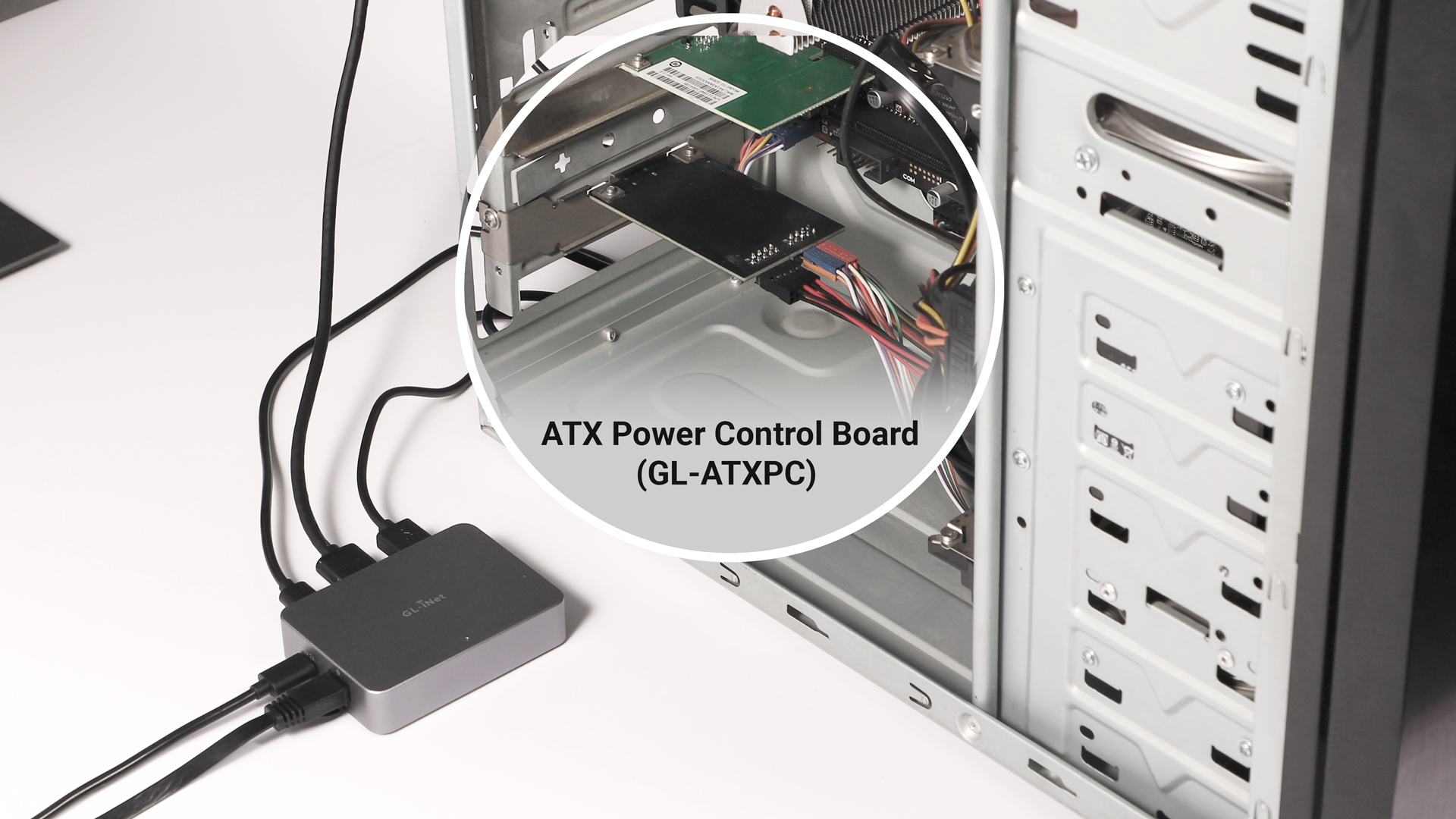
The ATX board is an optional accessory for GL.iNet KVM device. As a smart power management module, it enables remote control of the controlled device's power supply by simulating physical power button operations (power on/off/reboot).
The ATX board will be installed in the controlled device's chassis, providing more concealed and stable power management.
Package Contents
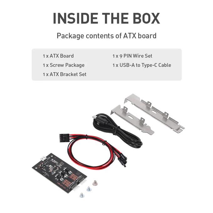
- 1 x ATX main board
- 1 x 9-PIN Wire Set
- 1 x Screw package
- 1 x USB-A to Type-C cable
- 1 x ATX Bracket Set
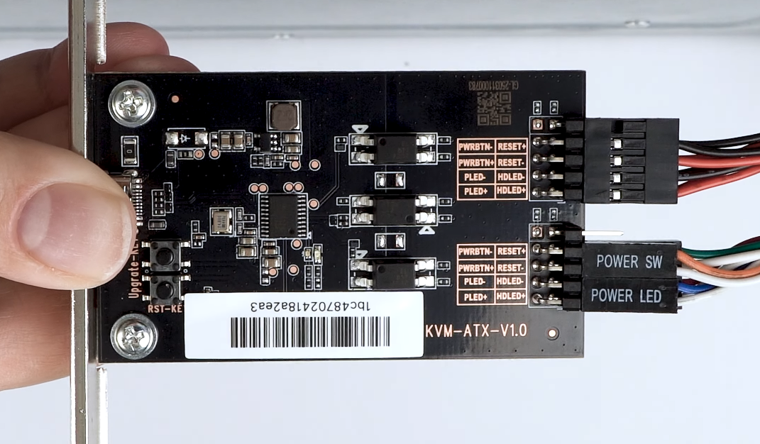
PIN-OUT
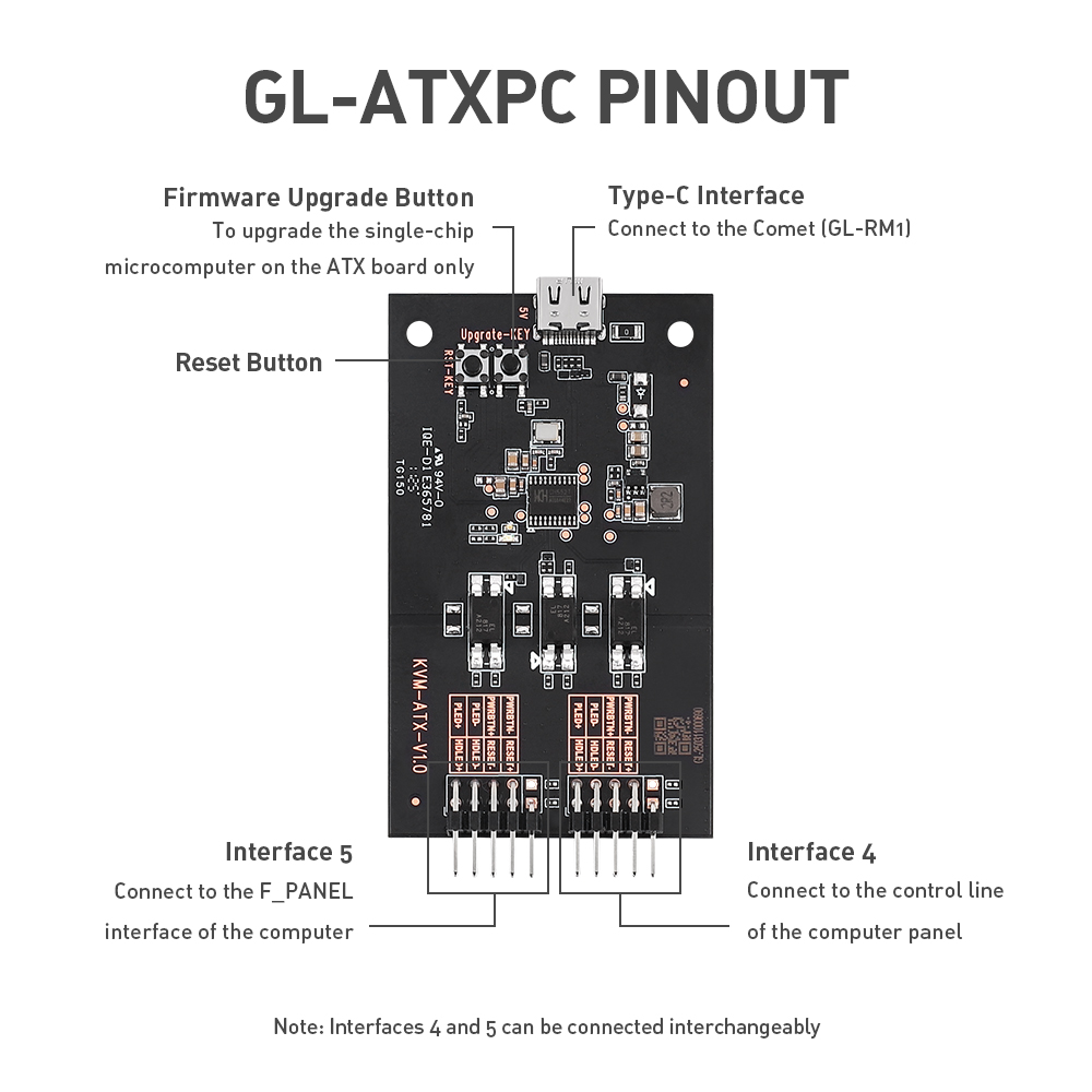
Explanation of Interfaces:
- Type-C Interface: Connect to the KVM device.
- Firmware Upgrade button: for the single-chip microcomputer on the ATX main board.
- Reset button.
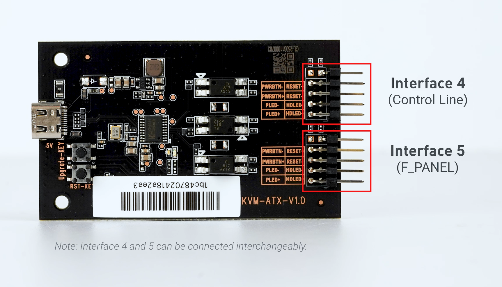
- Connect to the control line of the computer panel.
- Connect to the F_PANEL interface of the computer.
Note
-
Interfaces 4 and 5 can be connected interchangeably. That is to say, interface 5 can be connected to the control line of the computer panel, and interface 4 can be connected to the F_PANEL.
-
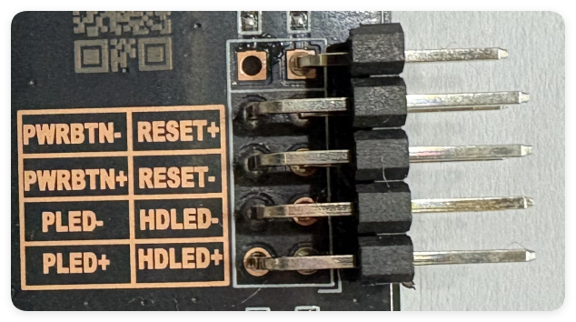
There are two LEDs on the ATX board, and both LEDs' behavior is the same as the Power LED (blue indicates the ATX system; green indicates PC power). There is no HDD LED on the ATX board. The LED status on the board is consistent with the Power LED status on the computer panel.
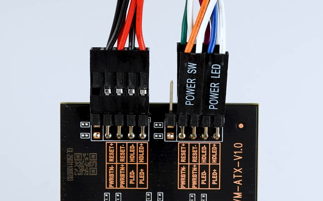
Interfaces 4/5 diagram:
Installation
Watch this video to install ATX board, or follow the steps below.
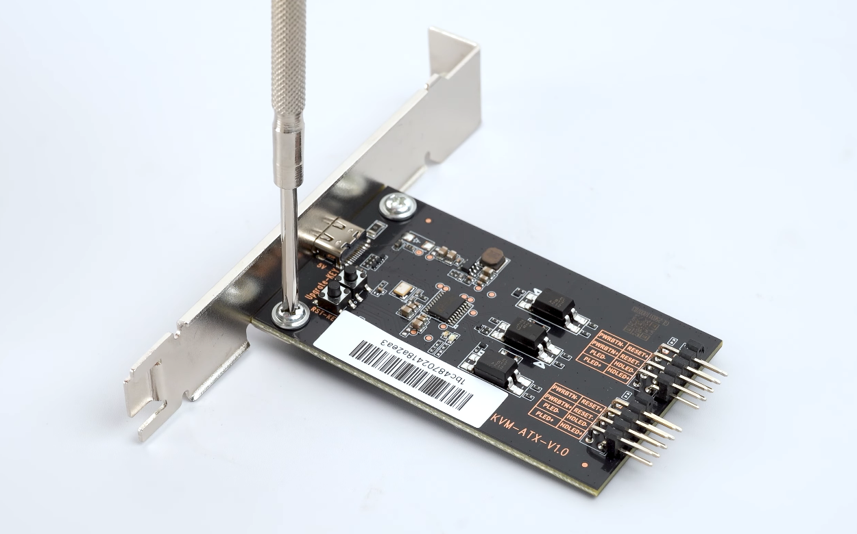
1. Screw ATX Board and Bracket
Fix the ATX board and the ATX Bracket Set with the screws provided.
2. Install ATX Board into PC Case
Connect interfaces 4 and 5 respectively to the controlled PC's control line and F_PANEL interface.
The 9-PIN Wire Set provided in the ATX Package allows you to connect one of the ATX board interface 4/5 to the controlled computer's control line or F_PANEL interface.
You need to use the wire set included in your computer case to connect another ATX board interface 4/5 to the controlled computer's control line or F_PANEL interface.
Note: The interface polarity may vary depending on different PC case. Please double check it before installation.
Below are some examples of connecting interface 4/5 to the F_PANEL interface of the controlled computer for your reference.
For 10-1 pin PANEL
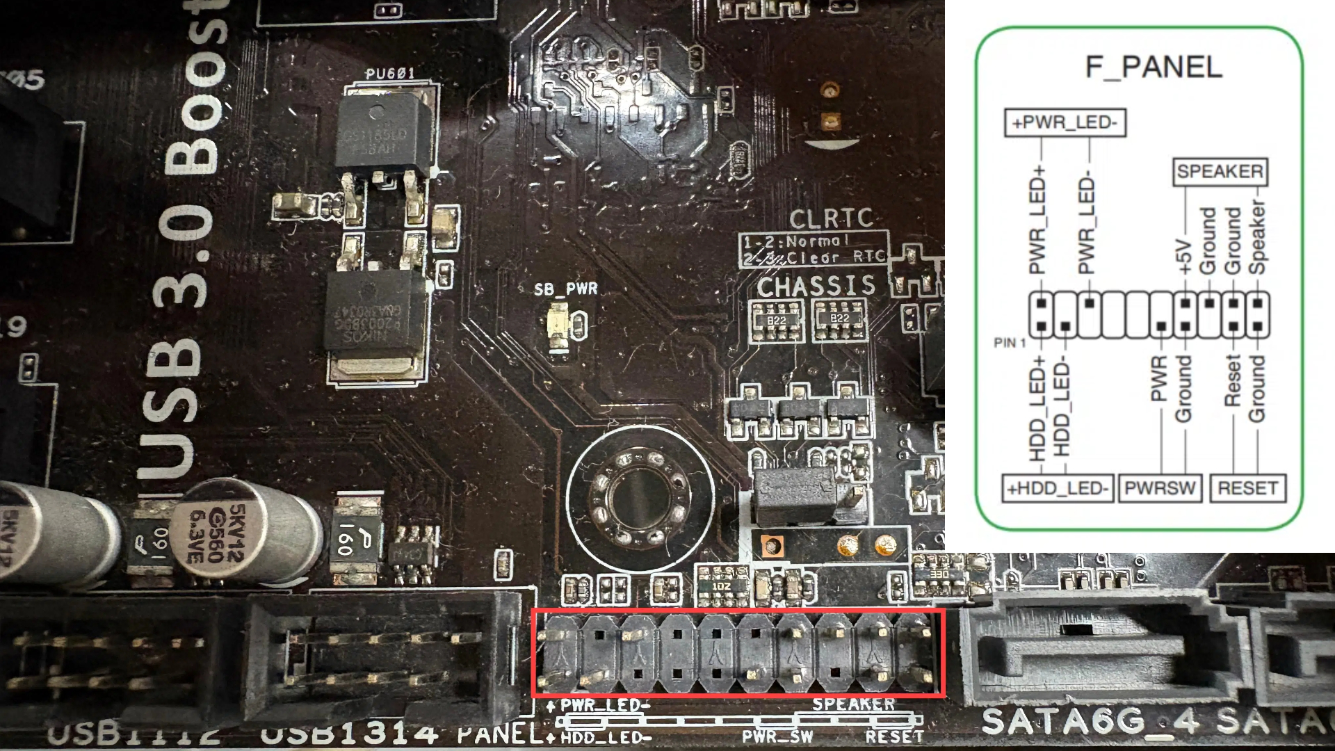
If the row of pins on your controlled computer's motherboard used to connect to the control panel is a 10-1 pin PANEL, as shown below.
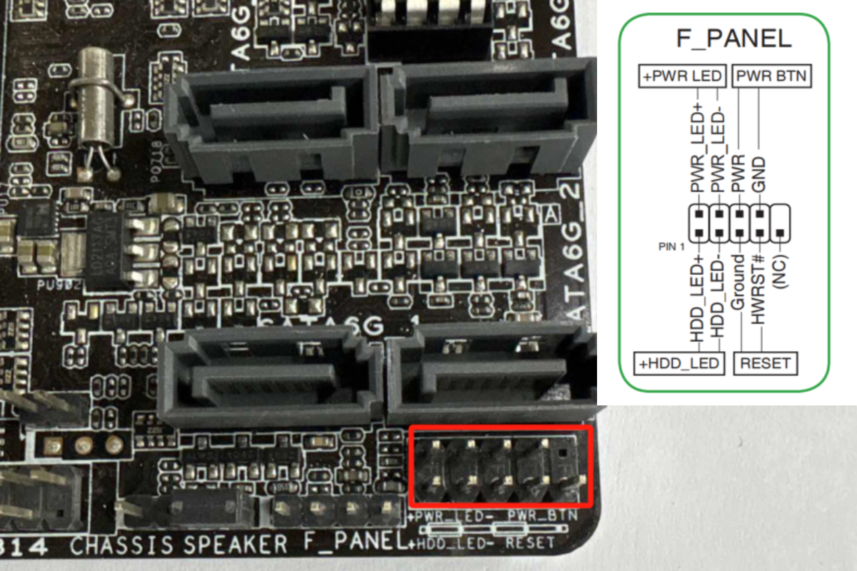
Please refer to the diagram below for connection, make sure that the silkscreen printing (i.e., the words HDDLED±, RESET SW, POWER SW, POWERLED+, etc.) is visible facing outward and not obscured facing inward.
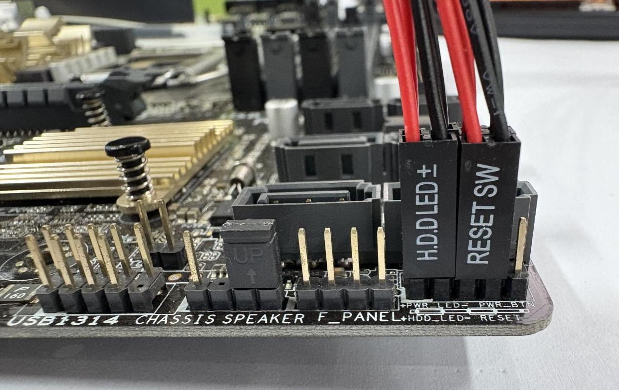 Front View
 Rear View
Then use the wire set included in your computer case to connect another ATX board interface to the computer control line.
For 20-5 pin PANEL
If the row of pins on your controlled computer's motherboard used to connect to the control panel is a 20-5 pin PANEL, as shown below.
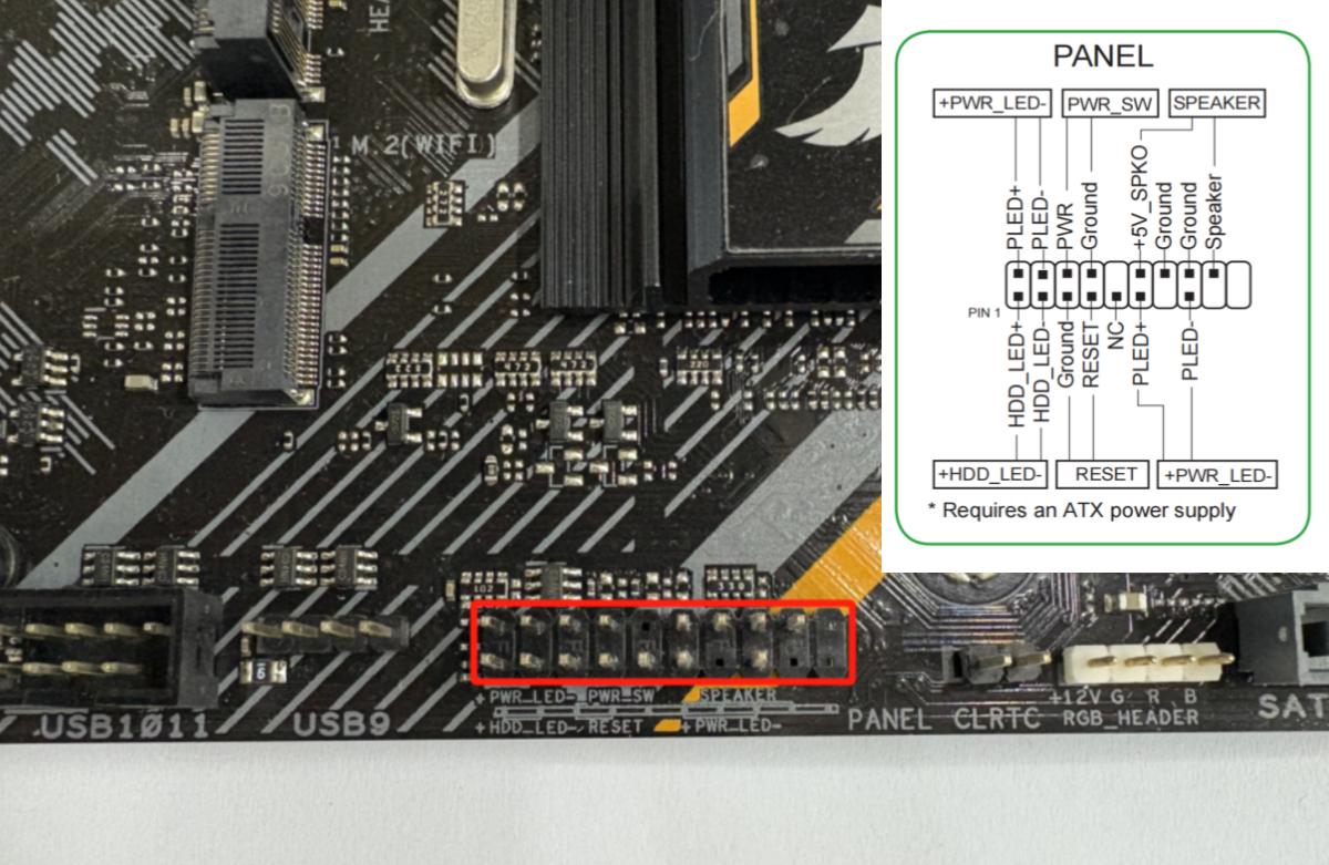
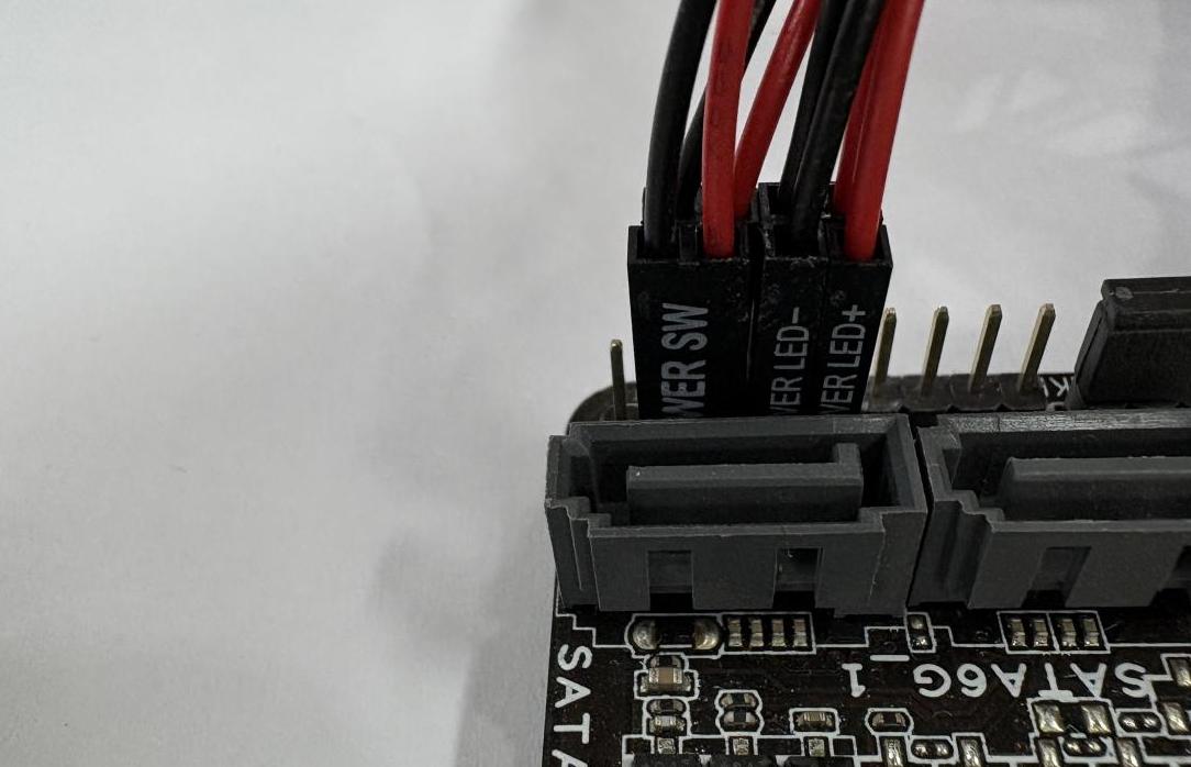
Please refer to the diagram below for connection, make sure that the silkscreen printing (i.e., the words HDDLED±, RESET SW, POWER SW, POWERLED+, etc.) is visible facing outward and not obscured facing inward.
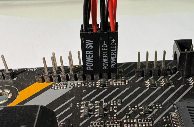
 Front View
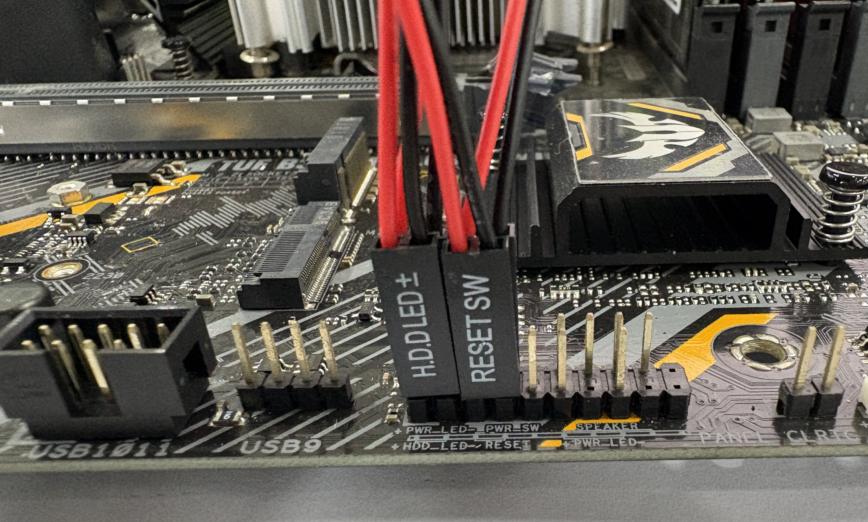
 Rear View
Then use the wire set included in your computer case to connect another ATX board interface to the computer control line.
For 20-8 pin PANEL
If the row of pins on your controlled computer's motherboard used to connect to the control panel is a 20-8 pin PANEL, as shown below.
Please refer to the diagram below for connection, make sure that the silkscreen printing (i.e., the words HDDLED±, RESET SW, POWER SW, POWERLED+, etc.) is visible facing outward and not obscured facing inward.

Then use the wire set included in your computer case to connect another ATX board interface to the computer control line.
The final connected ATX board is shown below.
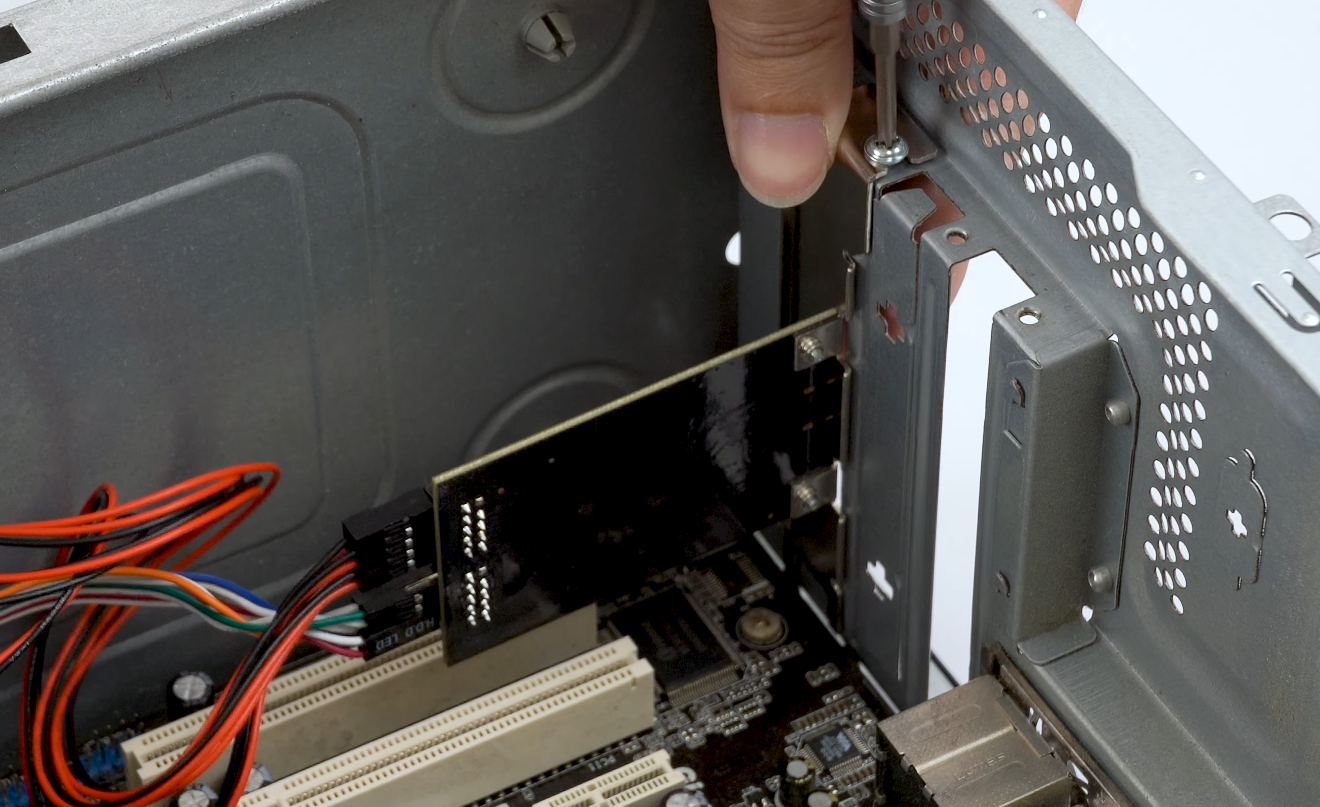
Then install the ATX board bracket into the computer case.
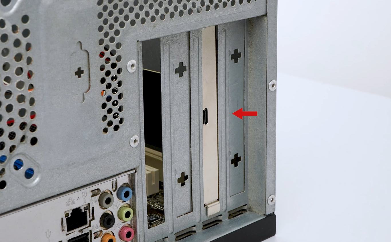
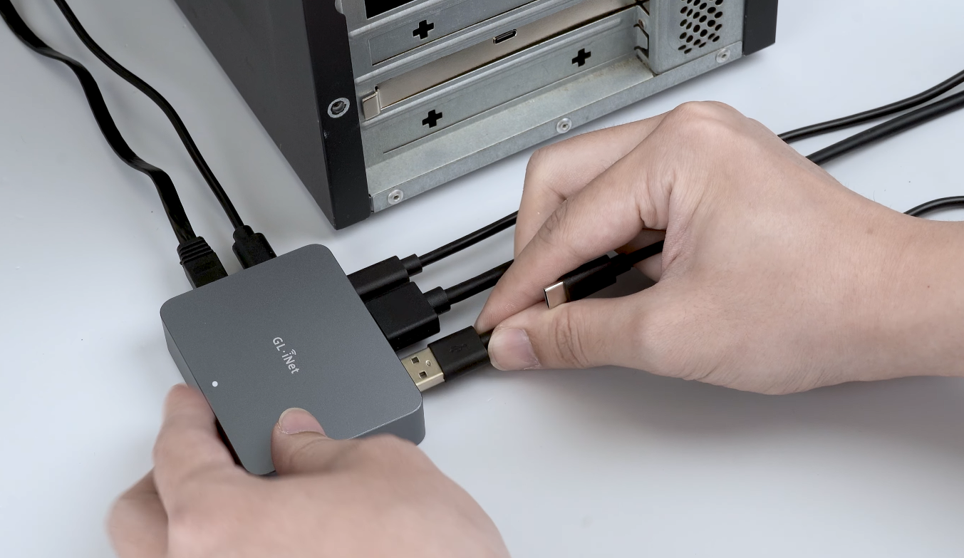
3. Connect ATX Board and KVM
Connect the Type-C port of ATX board to the USB-A port of the KVM device (such as Comet GL-RM1) using the included USB cable.
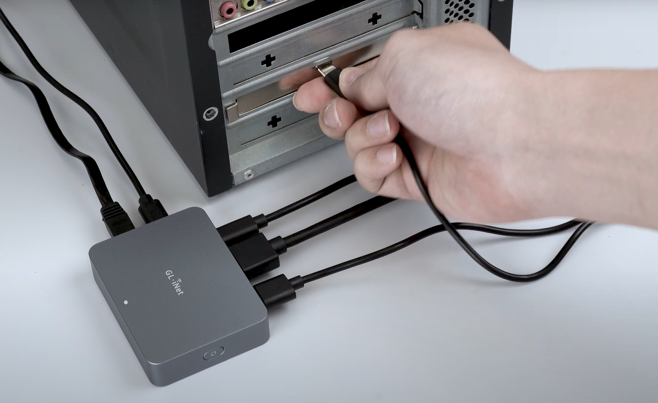
This completes the installation of the ATX board.
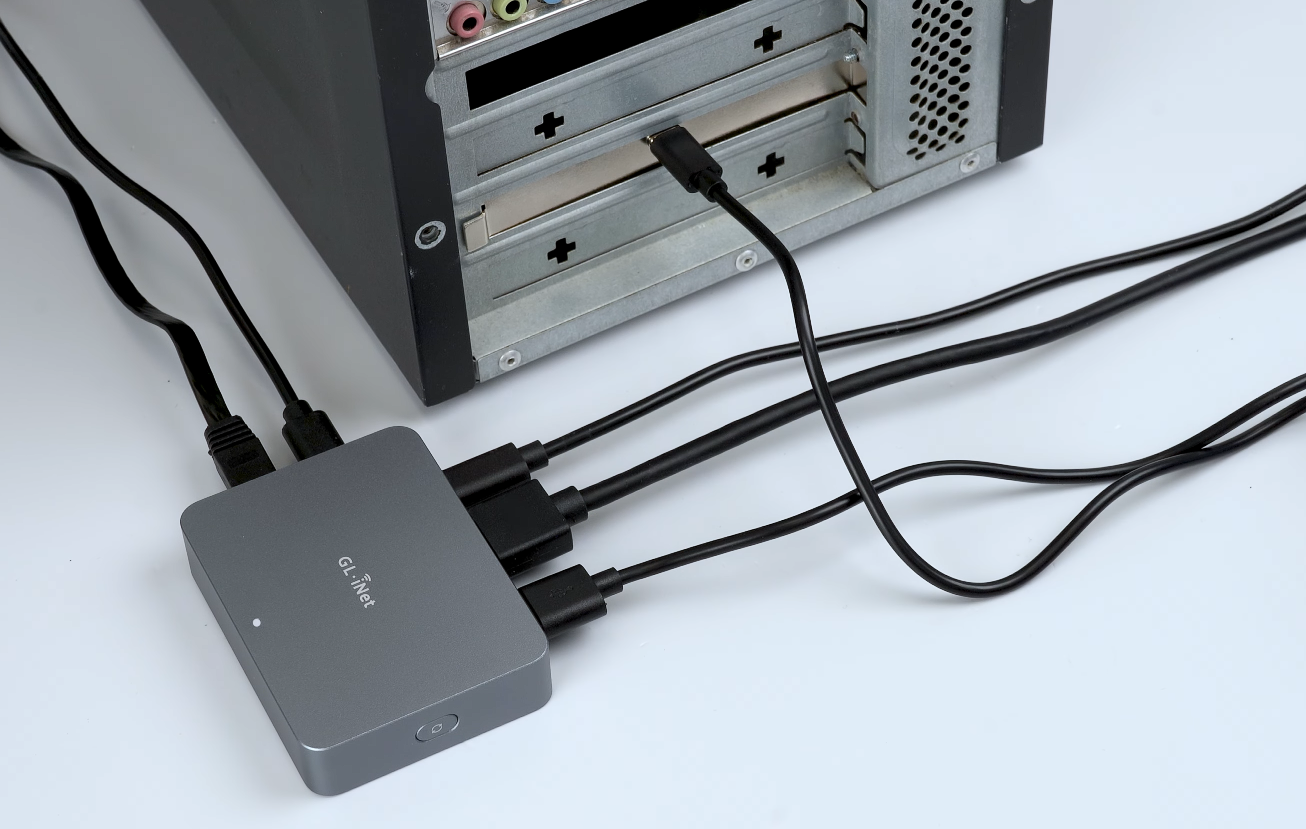
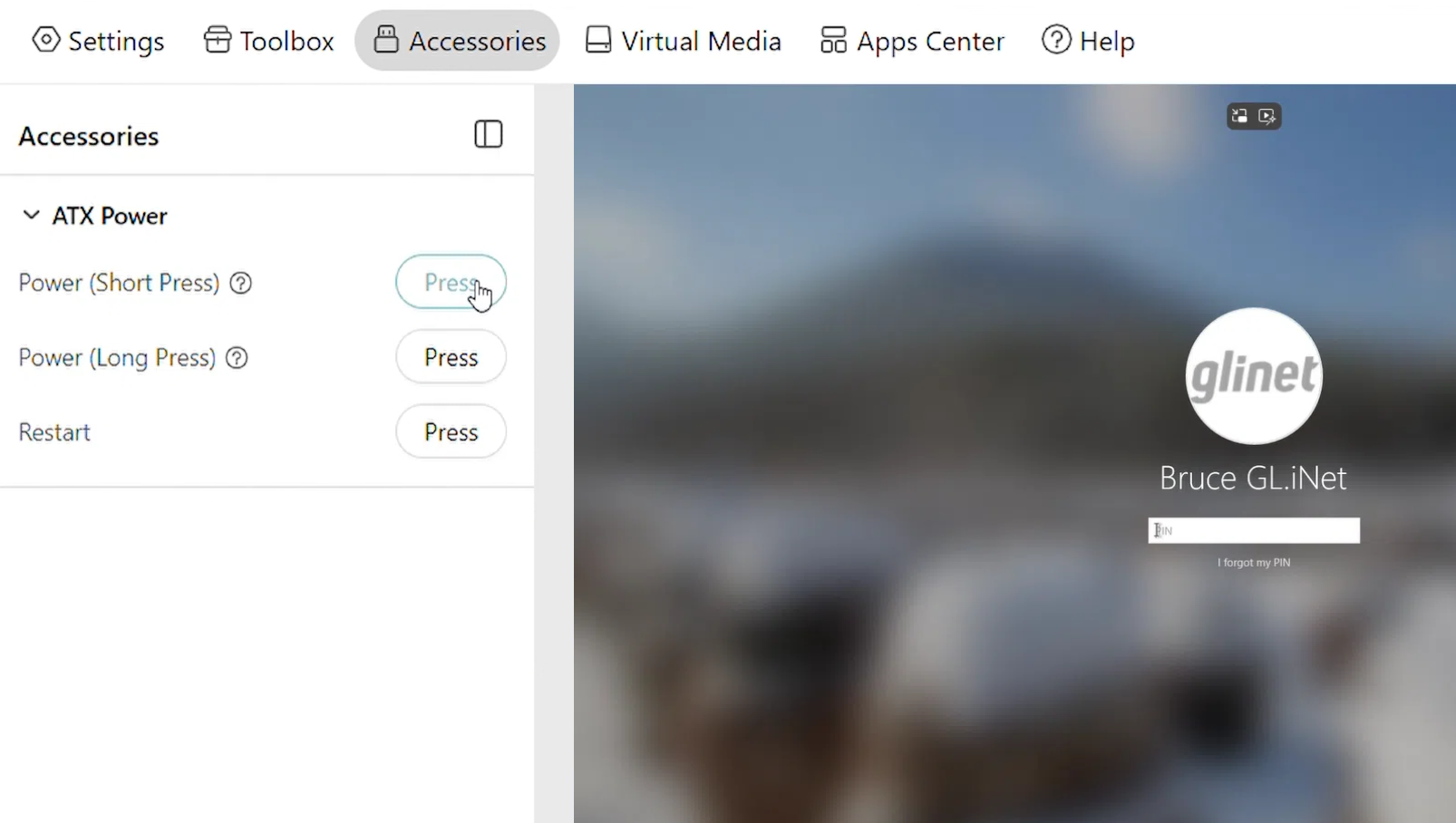
Now you can log in to your KVM, navigate to Accessories to control the ATX power.
FAQ
Q1. Can I use the GL-ATXPC board with non-GL.iNet KVM devices?
A1. No. GL-ATXPC board is an accessory for GL.iNet KVM devices. It should be used in conjunction with GL.iNet KVM.
Q2. After installing the ATX board, what should I do if I cannot control the remote device's power (on/off) via the KVM?
A2. Please try the following methods.
-
Ensure the controlled device can be powered on/off normally when the physical power button on the PC case front panel is pressed.
-
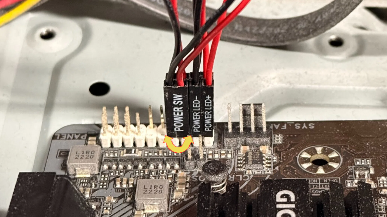
Check the wiring polarity. Try flipping the POWER SW connector polarity on the controlled device's motherboard to avoid incorrect wiring.
-
When connecting to the F_PANEL interface on the controlled device's motherboard, ensure the silkscreen printing (e.g., HDDLED±, RESET SW, POWER SW, POWERLED+, etc.) is visible facing outward, not obscured facing inward.
-
Upgrade the KVM's firmware.
Still have questions? Visit our Community Forum or Contact us.